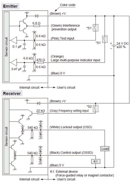
Ultra. Panasonic Ultra-slim Light Curtain [Type 2 PLc SIL1] SF2C product information www3.panasonic.biz

Basic electrical design of a PLC panel (Wiring diagrams) . It is uncommon for engineers to build their own PLC panel designs (but not impossible of course). For example, once the electrical designs are complete electrical-engineering-portal.com

PLC Circuit Diagram. program-plc.blogspot.com

Plc Wiring Basics . Plc wiring basics siezendevisser.nl

Programmable logic . electronics.stackexchange.com

The circuit diagram of the PLC auto power reset From Figure 2, the PLC... . Download scientific diagram | The circuit diagram of the PLC auto power reset From Figure 2, the PLC auto power reset circuit consists of the microprocessor monitor IC (MAX1232) and precision timer, LM555N. The board was built and installed in the mono-stereo controller. The new controller was tested at IBB transmitting station in Thailand for 6 months before it was replaced the old one at Mongolia in August 2013. The mini PLC from the Array model AF-10MR-E was also internally modified by removing the relay at Q4 to reduce the noisy from the relay contact. Also, the new software is programmed to the PLC to generate the clock of 50 msec when it is in normal operation. Since, the IC, MAX1232 is used as watchdog timer, the clock pulse from the PLC must toggle the strobe input (pin 7) within a timeout period of 1,200 msec which is determined by time delay (TD) per electrical characteristics of the chip. The longest time delay which is 1,200 msec can correctly read the status of the PLC if it really stops working. When the PLC is frozen, the sequence of the reset takes 1 second to restart the PLC during the night or day time without manned assistance. The regulator power supply that is used by the PLC auto power reset circuit is also built in the mono-stereo controller and externally wired via D9-type connector to the PLC. The switch 1 (SW1) is wired to the output of the PLC (Q1) and is switched to manual position for time synchronization by manual. The SW1 must always be set at auto position to allow the remote terminal that can automatically synchronize the clock of the PLC. Also, it can be done by the remote terminal from Thailand transmitting station or anywhere that has internet access every 3 months. From the circuit diagram, the U1 is voltage regulator which is used to regulate voltage from the power supply 12 voltages to provide 5 voltages for U2 and the U2 is microprocessor monitor chip (MAX1232) that is used to monitor the 50 msec clock from the PLC. The U3 is the precision timer, LM555N that is used to remove the power from the relay1 when there is no clock from the PLC. The U4 is the precision timer that is used to energize the relay2 for 1.08 sec to provide 12 voltages to the PLC while is being restarted. The D1 is redrawn as LED2 used to monitor the 50 msec  from publication: Design of programmable logic controller auto power reset circuit for FM transmitter | The mono-stereo controller using audio mute clock is used at the International Broadcasting Bureau (IBB) FM 106.6 MHz transmitter in Ulaan Baatar, Mongolia since 2010. The major problem of the FM broadcast station was from the frozen Programmable Logic Controller, PLC, which... | Programmable Logic Controllers, PLC and Circuits | ResearchGate, the professional network for scientists. www.researchgate.net